 ar
ar bg
bg hr
hr cs
cs da
da nl
nl fi
fi fr
fr de
de el
el hi
hi it
it ko
ko no
no pl
pl pt
pt ro
ro ru
ru es
es sv
sv tl
tl iw
iw id
id lv
lv lt
lt sr
sr sk
sk sl
sl uk
uk vi
vi et
et hu
hu th
th tr
tr fa
fa ms
ms hy
hy ka
ka ur
ur bn
bn mn
mn ta
ta kk
kk uz
uz ku
ku
load cell wire diagram
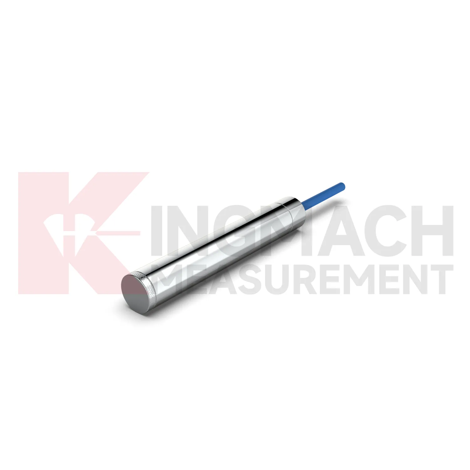
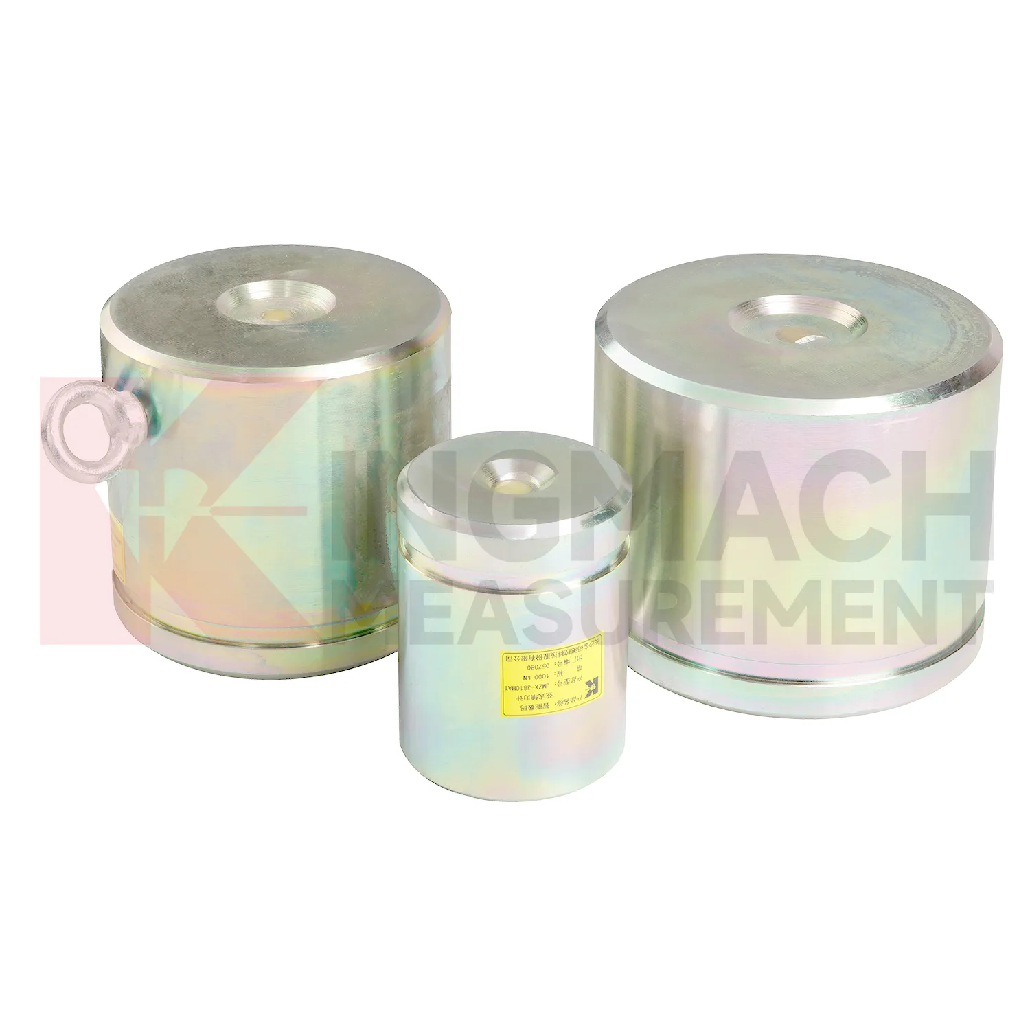
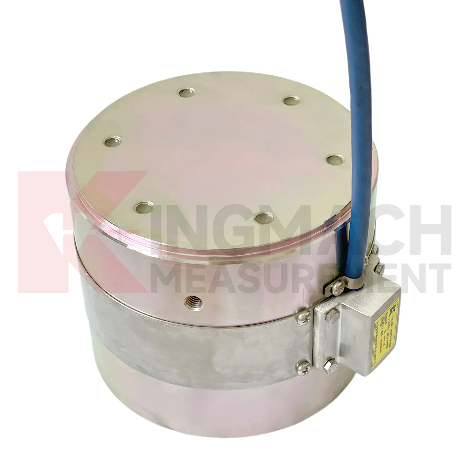
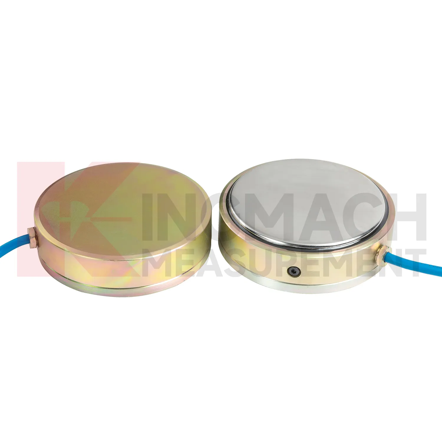
Kingmach load cell wire diagram is suitable for projects that need both high capacity and traceable readings. The solid JMZX-35XXHAT line lists a 0.5%FS precision rating, a -30°C to 80°C temperature range, and overload information up to 20 to 50%F.S. for range overload and 300 to 400%F.S. for failure overload. The hollow JMZX-3XXXHAT line lists a 50 year design life, waterproof durability, digital output, and storage for 800 measurement records. The axial force JMZX-38XXHAT line lists 1 MPa waterproofing and direct kN display. Together, these points support force measurement in bridges, buildings, railways, transportation, hydropower, dams, tunnels, and foundation pits. Kingmach also provides monitoring products beyond load measurement, allowing the force record to be compared with movement, pressure, and environmental data. That is useful when a load change needs to be judged against the wider behavior of the structure rather than treated as a disconnected alarm. Kingmach's product pages also refer to industry certifications such as GB/T 13606-2007 and DL/T 269-2022 on selected models. Such references help buyers request documentation that matches project acceptance procedures and owner audit needs. This helps avoid ordering a sensor that is strong enough on paper but difficult to seat, wire, read, or protect in the actual structure.
Application of load cell wire diagram
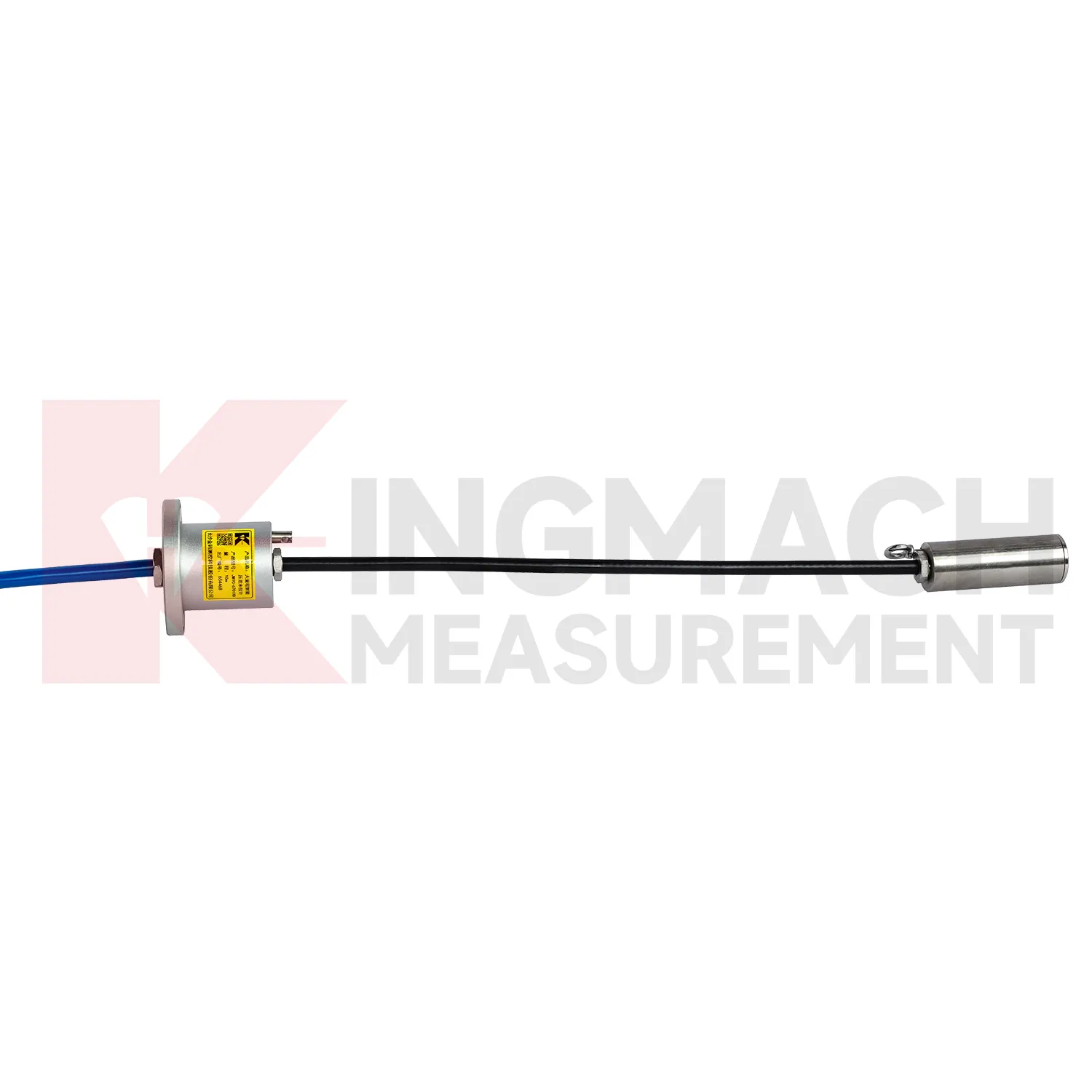
In industrial force testing and heavy equipment monitoring, load cell wire diagram can be applied to presses, jacks, lifting frames, cranes, test benches, fixtures, and custom loading rigs. The pain point is repeatability. A test may pass once, but the owner needs to know whether the next test used the same loading path, sensor range, and calibration basis. Kingmach solid load cells provide high capacity force measurement up to 10000 kN with 0.5%FS precision, while hollow load cells cover 500 kN to 8000 kN and can store 800 measurement records on smart models. Axial force meters provide 200 kN to 3000 kN ranges and direct kN display. These features suit both site acceptance testing and repeated equipment checks. Installation should control centering, bearing plate flatness, side loading, cable strain relief, and zero reading before load is applied. Data becomes stronger when the report records operator, fixture condition, load stage, temperature, and any overload event. For test benches, repeatability also depends on fixture stiffness, alignment, and loading rate. A high accuracy sensor cannot correct a poor mechanical setup, so maintenance should include the test frame and not only the measuring element. The monitoring plan should also define who reviews abnormal data and how quickly a field check must follow a confirmed alarm.
The future of load cell wire diagram
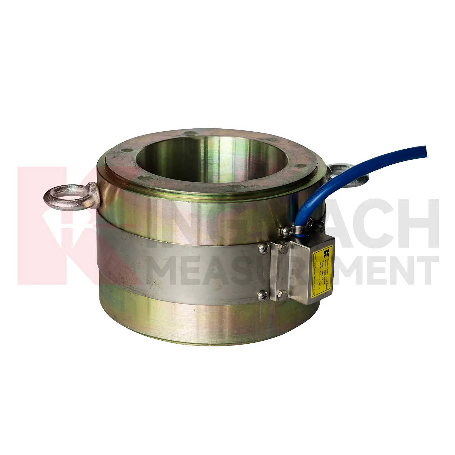
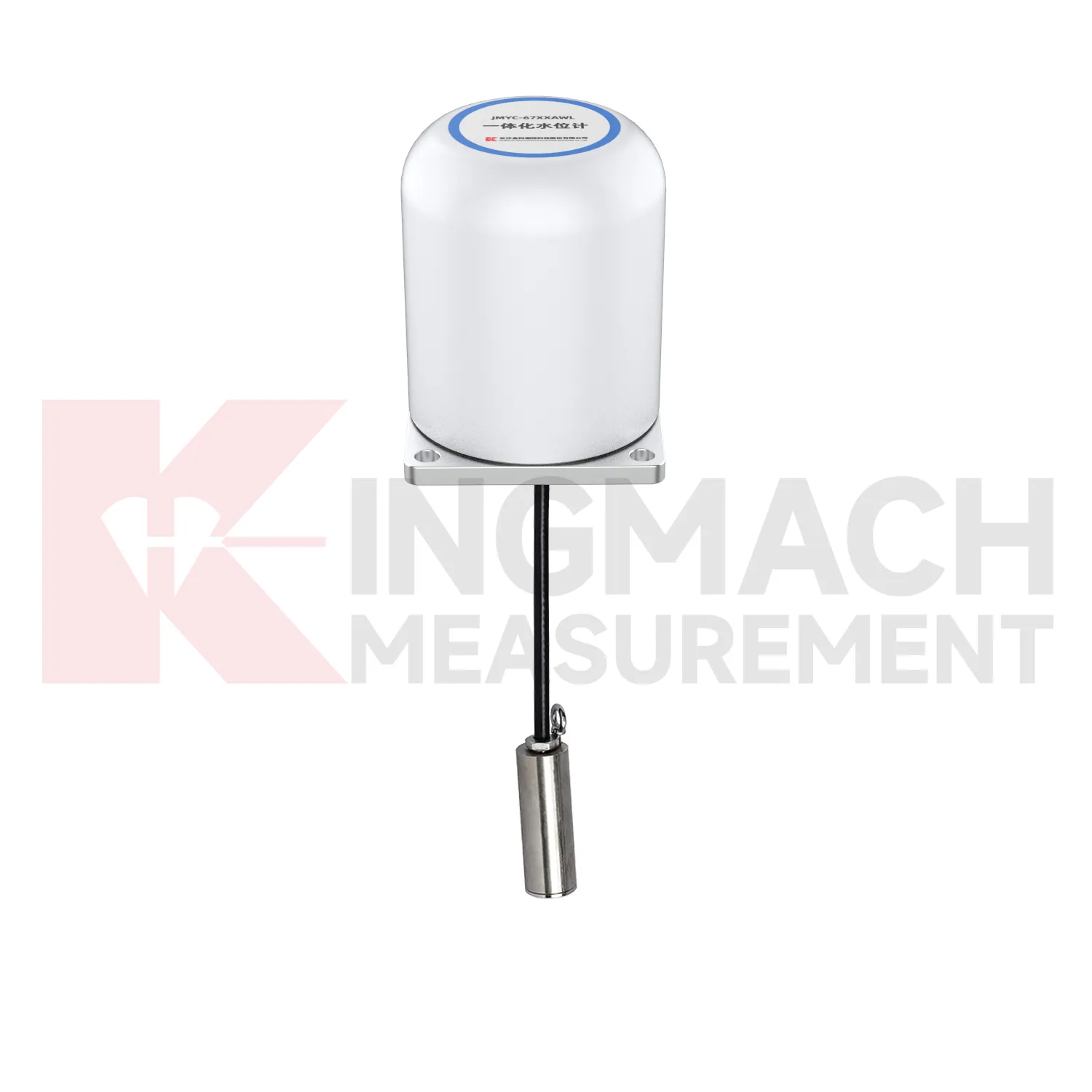
Geotechnical use of load cell wire diagram will become more connected to environmental monitoring. Earth pressure cells with 0.3 MPa to 8 MPa ranges and 0.001 MPa resolution can already record soil or contact pressure, but future value comes from reading pressure with rainfall, groundwater, seepage, settlement, and slope movement. A pressure increase after rain may be acceptable in one slope and worrying in another, depending on the ground model and drainage condition. Digital twins can handle that comparison if the data is clean enough. Kingmach's wider catalog, including piezometers, water level meters, settlement sensors, tiltmeters, data loggers, and visualization software, supports that direction. Wireless communication will help remote slopes and embankments, while wired systems may remain preferable for buried points with long service expectations. Future standards for monitoring reports will likely ask for more traceable context around each reading, including sensor range, accuracy, calibration date, and installation depth. That connection makes trend review more useful after storms.
Care & Maintenance of load cell wire diagram
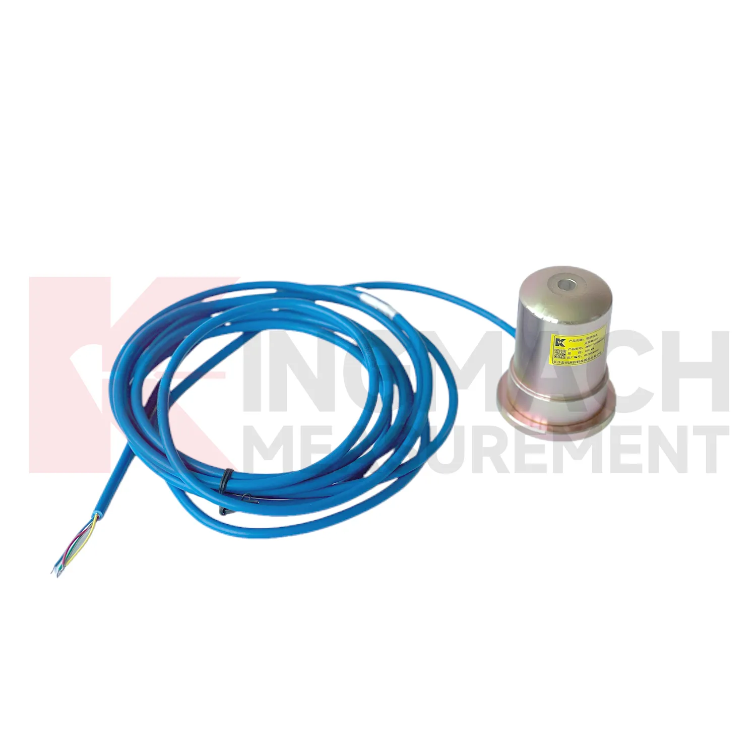
For load cell wire diagram used with manual readouts, care depends on repeatable procedure. Before installation, store the calibration sheet with the instrument and confirm that the readout supports the sensor type. Kingmach product pages mention compatible readouts and comprehensive vibrating wire instruments, which can display force values directly on selected models. During installation, label the cable and channel clearly, record the zero value, and protect the connection point from water and pulling. During each reading round, use the same unit, readout setting, point name, and observation sequence. Note temperature, weather, construction activity, and any visible damage near the sensor. Long term maintenance should include connector cleaning, cable jacket inspection, comparison with nearby points, and periodic calibration planning according to project requirements. If a reading seems wrong, repeat it after checking the cable and readout battery. Many apparent sensor faults come from swapped channels, loose connectors, or missing zero records. Use the same readout settings.
Kingmach load cell wire diagram
load cell wire diagram helps remove guesswork from load transfer, especially during construction stages that move quickly. Excavation, jacking, prestressing, concrete placement, reservoir impoundment, and staged traffic opening can all change force paths in hours. Kingmach smart sensor designs support digital output, long distance transmission, memory functions, and temperature correction on relevant models, which helps when manual reading windows are short. The point is not to collect more numbers for their own sake. The point is to catch a force trend early enough for the site team to check alignment, bearing plates, strut preload, grouting, drainage, or support sequence. A well installed sensor also leaves a handover trail for the owner. Later, when the structure enters service, the same point can be reviewed against seasonal effects and maintenance inspections. This keeps the force record tied to engineering behavior instead of scattered site notes. It should also record who accepted the first reading and which site event should trigger the next comparison.
FAQ
Q: What does load cell wire diagram do in a foundation pit or tunnel? A: It measures axial force in steel supports, anchor load, or pressure change as excavation and support stages progress. Q: Which Kingmach model fits steel support axial force? A: The JMZX-38XXHAT axial force meter is listed from 200 kN to 3000 kN, with 0.1 kN or 1 kN sensitivity and 0.5%FS accuracy. Q: Is it suitable for wet underground sites? A: The axial force meter lists a 1 MPa waterproof rating, but connector sealing and cable routing still need inspection. Q: Why is direct kN display useful? A: It reduces confusion because teams can read axial force directly instead of converting vibrating wire frequency on site. Q: What should trigger extra checks? A: Excavation step changes, rainfall, dewatering, support adjustment, sudden force jumps, or unstable channels.
Reviews
Joshua Clark
We ordered a full monitoring solution including sensors and data loggers. Everything works seamlessly together. Great supplier!
James Thompson
The tiltmeters and accelerometers are very sensitive and provide precise data. Perfect for our structural health monitoring system.
Latest Inquiries
To protect the privacy of our buyers, only public service email domains like Gmail, Yahoo, and MSN will be displayed. Additionally, only a limited portion of the inquiry content will be shown.
Amelia***@gmail.comSingapore
Hello, I am looking for visualization software for monitoring system data analysis. Please let me kn...
Isabella***@gmail.comGermany
Hello, we are evaluating weir flow meters for a water management project. Please share accuracy deta...