 ar
ar bg
bg hr
hr cs
cs da
da nl
nl fi
fi fr
fr de
de el
el hi
hi it
it ko
ko no
no pl
pl pt
pt ro
ro ru
ru es
es sv
sv tl
tl iw
iw id
id lv
lv lt
lt sr
sr sk
sk sl
sl uk
uk vi
vi et
et hu
hu th
th tr
tr fa
fa ms
ms hy
hy ka
ka ur
ur bn
bn mn
mn ta
ta kk
kk uz
uz ku
ku
load cell force
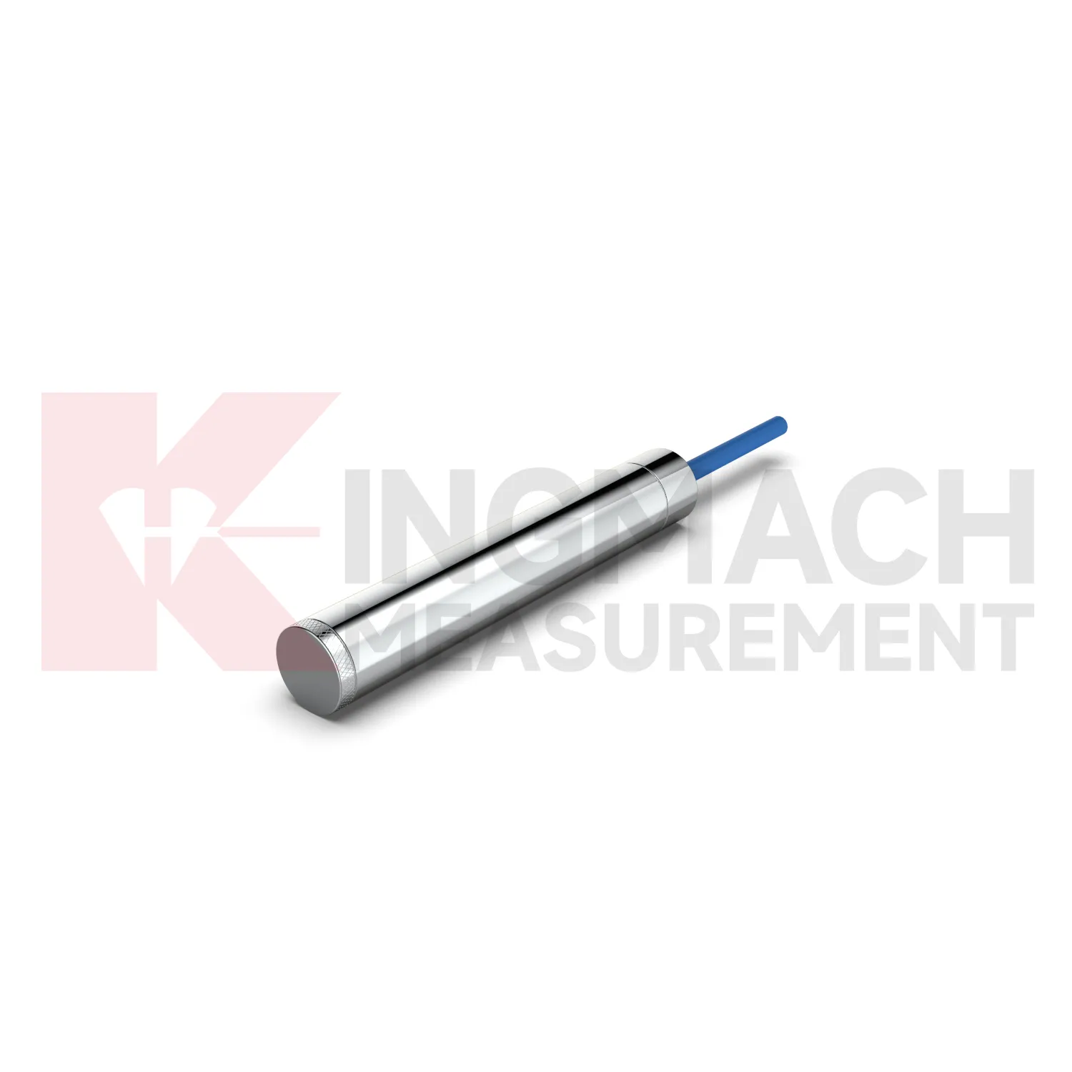
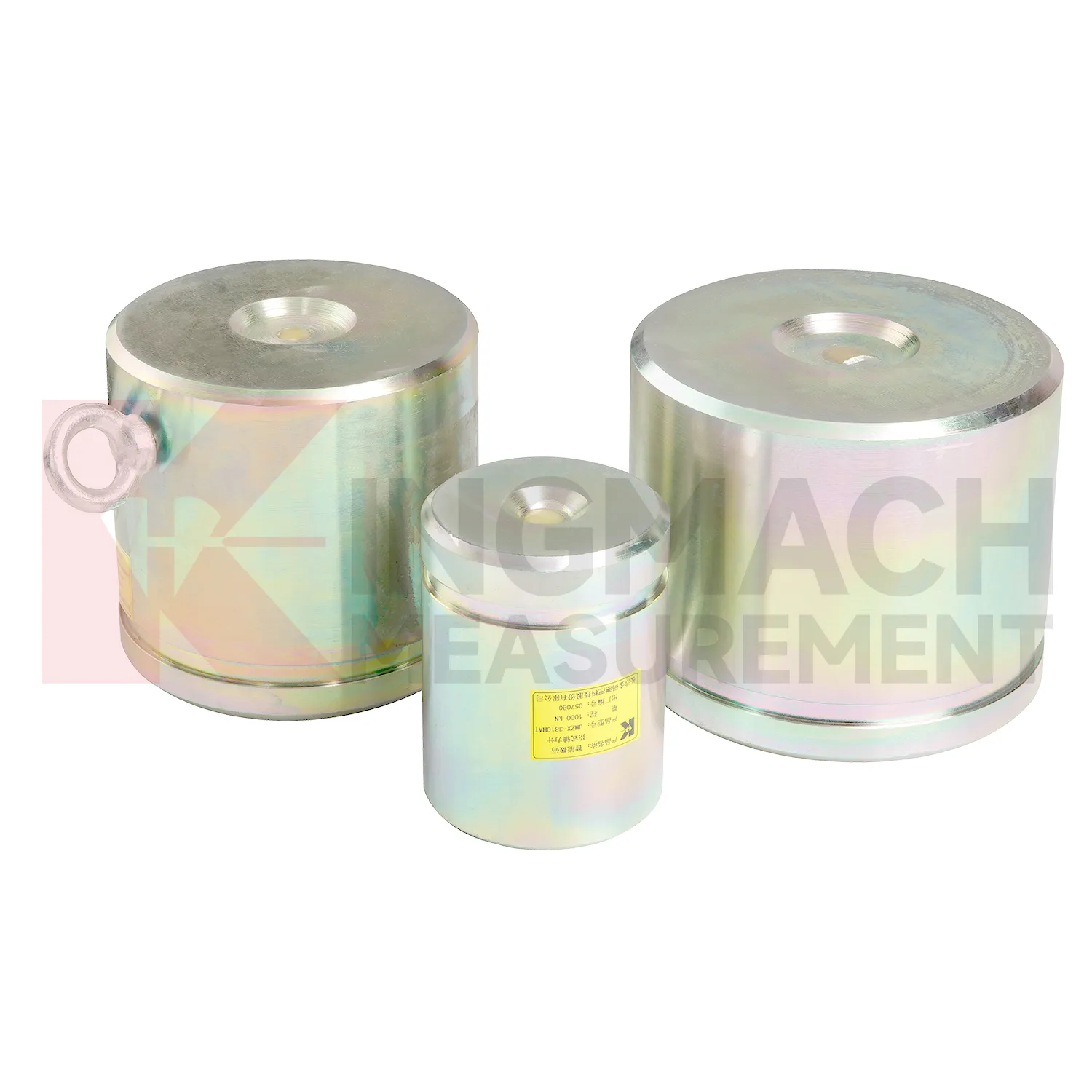
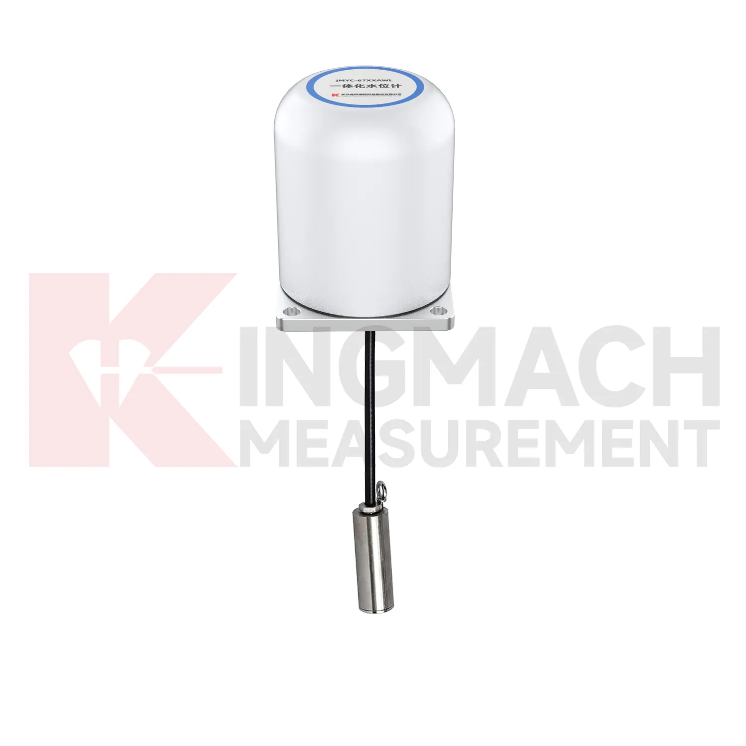
Kingmach load cell force can be specified as part of a complete monitoring workflow rather than as a standalone instrument. Product pages mention manual readout compatibility, comprehensive vibrating wire readouts, automated acquisition, and storage of model or calibration information inside smart sensors. On listed models, force ranges extend from 200 kN on smaller axial force meters to 10000 kN on high capacity solid load cells, while pressure related models cover 0.3 MPa to 8 MPa. The presence of temperature correction, waterproof construction, digital output, and stable vibrating wire sensing helps the same installation work through construction and service periods. Kingmach's support range includes data loggers, instrumentation cables, and visualization software, so project teams can plan channel naming, alarm limits, report format, and maintenance inspection around the sensor from the beginning. That reduces later confusion when hundreds of monitoring points are installed across a bridge, subway, dam, slope, or foundation project. Viewed as a package, the product, readout, cable, calibration record, and software connection all affect data quality. Kingmach's catalog structure helps buyers think about that whole chain rather than treating the sensor as a loose component. For long projects, that shared record reduces confusion when installation teams, monitoring teams, and maintenance teams are not the same people.
Application of load cell force
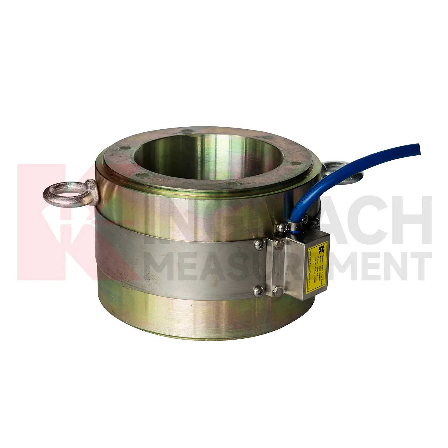
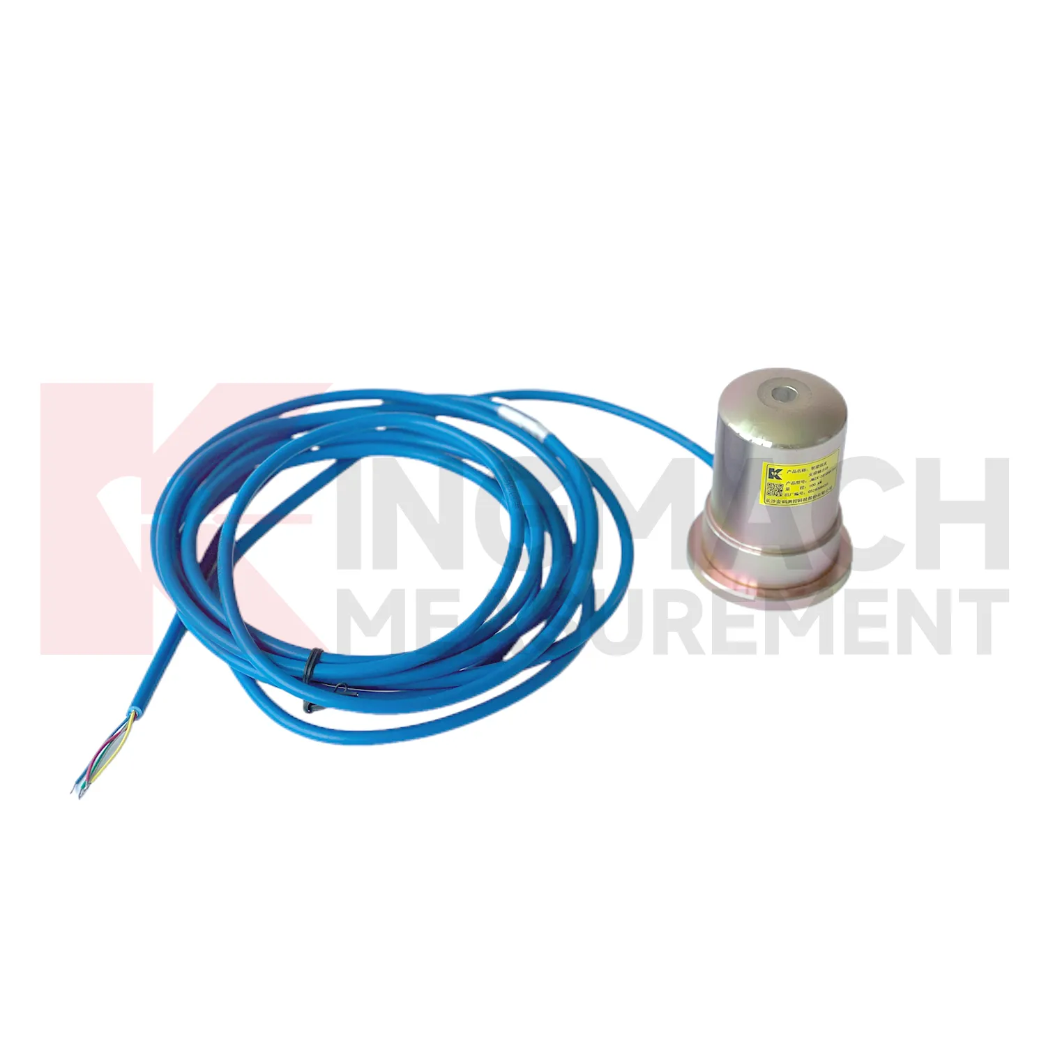
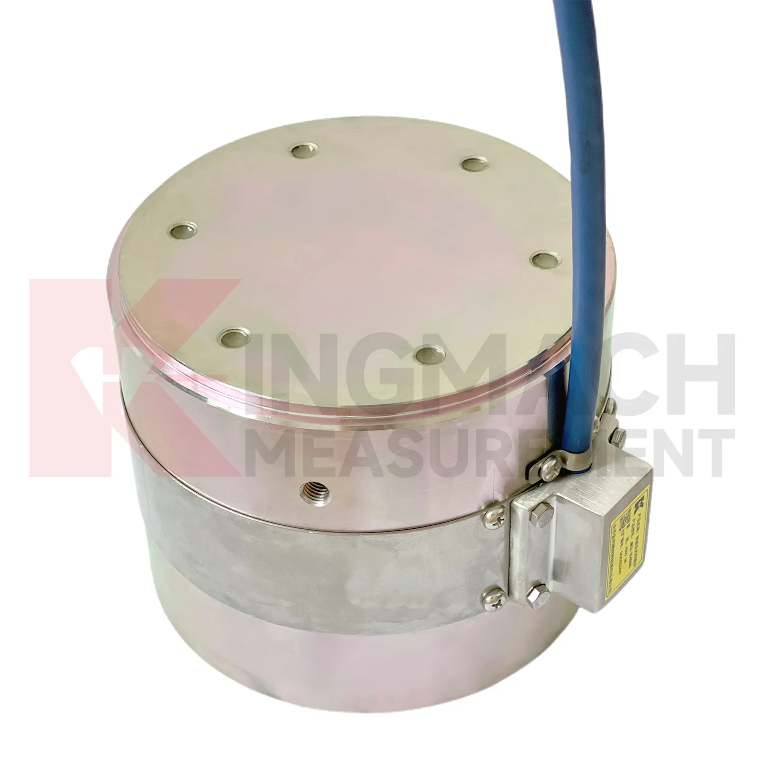
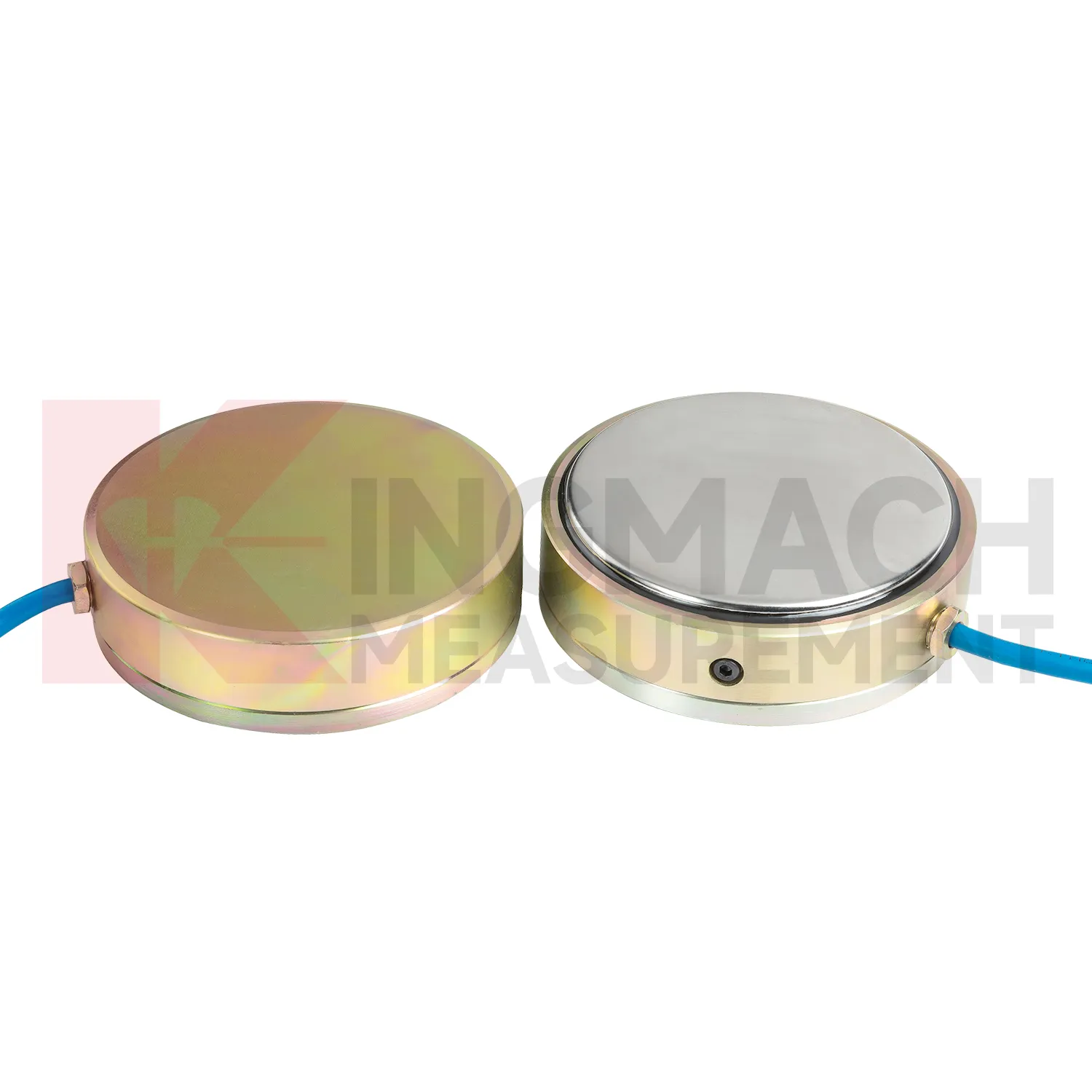
In dam and hydropower monitoring, load cell force can be used for anchor force, concrete bearing pressure, gate structure load checks, earth pressure near embankments, and long term load review around seepage control areas. The monitoring difficulty is durability. Access may be limited, water influence is persistent, and seasonal temperature changes can mask small force trends. Kingmach hollow load cells list a 50 year design life, waterproof durability, automatic temperature correction, digital output, and 800 stored measurement records. Earth pressure cells also list a 50 year design life, 0.5%FS pressure accuracy, and ±0.5°C temperature accuracy. These parameters support long observation periods, especially when readings are tied to reservoir level, seepage, rainfall, and temperature records. For dam owners, a single force value is rarely enough. The trend should show whether anchors remain stable, whether pressure increases after impoundment, and whether unusual readings appear near maintenance or water level changes. Automated acquisition is often worth planning where manual access is costly. For long service assets, the monitoring plan should also say who checks the reading after storms, earthquakes, reservoir level changes, or maintenance work. A sensor that is never reviewed at the right moment does not give the owner much protection.
The future of load cell force
Future load cell force design will keep moving toward lower maintenance without making the device harder to verify. Waterproof structures, high strength vibrating wires, automatic temperature correction, and smart chips already reduce field workload on Kingmach models. The next steps may include better connector sealing, self-diagnosis of signal quality, power efficient acquisition, and cleaner integration with cloud platforms. For remote dams, slopes, bridges, and rail corridors, LoRa, 4G, satellite, or wired hybrid systems may be selected according to access and power conditions. Long term data also needs stable units, channel names, calibration files, and inspection notes. Without those, a smart sensor can still produce a confusing record. Future procurement may therefore ask for sensor performance and data governance together: range, accuracy, service life, waterproof rating, memory, communication method, and exportable records. Kingmach's broad monitoring catalog is well positioned for this combined hardware and data requirement. Long life hardware still needs verifiable records around it.
Care & Maintenance of load cell force
For load cell force installed in foundation pits or tunnels, the maintenance routine must fit a fast changing site. Axial force meters may cover 200 kN to 3000 kN with 0.5%FS accuracy and direct kN display, while earth pressure cells may cover 0.3 MPa to 8 MPa with 0.001 MPa resolution. During installation, confirm that steel support surfaces have enough thickness and strength, and add buffer plates where stress concentration is possible. Protect the sensor body and cable from equipment impact, cutting, concrete splash, and standing water. During excavation, check readings after each major stage rather than waiting for a fixed calendar date. If a channel becomes unstable, inspect the cable route, connector, readout, and temperature condition first. Long term points should have waterproof labels, photo records, and clear channel mapping. Sudden changes should be compared with wall movement, settlement, water pressure, and site work before any conclusion is recorded.
Kingmach load cell force
load cell force often sits between design intent and field behavior. Drawings may state the expected force, but site loading can change when excavation sequence, concrete curing, traffic, reservoir level, grouting, or prestressing work changes. Kingmach supplies sensors and acquisition equipment for bridges, tunnels, dams, subways, slopes, foundations, railways, buildings, and hydropower projects. In these settings, the sensor helps reveal whether a member is carrying its share of the load or taking more than expected. The instrument must fit the force range, the bearing surface, the environmental exposure, and the data workflow. A high capacity sensor with poor installation records is still hard to trust. A moderate range sensor with clear calibration, stable zero, protected cable, and a clean reading plan can produce stronger evidence. For that reason, force monitoring should be planned alongside installation details, not added after the site has already become crowded. This is especially useful when the monitored point becomes hidden after the next work stage.
FAQ
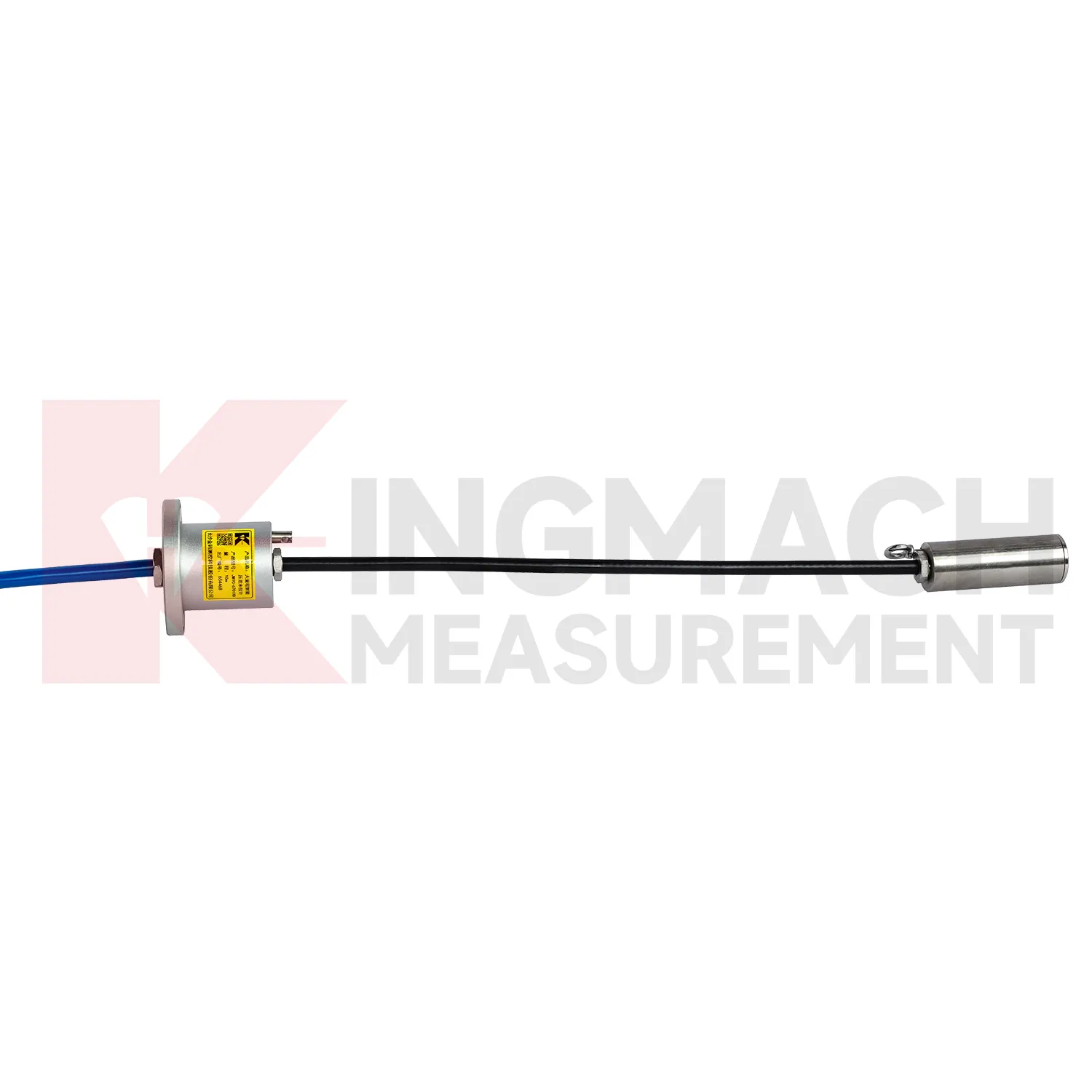
Q: How should load cell force be selected for a bridge cable or anchor point? A: Start with expected force, lock-off load, possible overload, bearing geometry, and access for later inspection. Hollow load cells are commonly used where the anchor or cable passes through the center opening. Q: What range information is available from Kingmach hollow models? A: The JMZX-3XXXHAT series is listed from 500 kN to 8000 kN, with 0.1 kN sensitivity on the 500 kN model and 1 kN on larger listed models. Q: Why does temperature correction matter? A: Cable and anchor readings can move with temperature, so built-in temperature measurement helps reduce false interpretation. Q: Can readings be stored inside the sensor? A: Smart hollow models list storage for 800 measurement records, including time, temperature, zero values, and correction data. Q: What should be checked after installation? A: Check seating, cable protection, connector sealing, zero value, first stable force, and matching channel name.
Reviews
Michael Anderson
The strain gauges and load cells are extremely accurate and stable. They performed very well in our bridge monitoring project. Highly recommended!
David Wilson
We purchased displacement transducers and settlement sensors, and the quality exceeded our expectations. Easy installation and reliable performance.
Latest Inquiries
To protect the privacy of our buyers, only public service email domains like Gmail, Yahoo, and MSN will be displayed. Additionally, only a limited portion of the inquiry content will be shown.
Harper***@gmail.comIndia
Dear Sir, we are planning to procure a complete monitoring system including strain gauges, tiltmeter...
Olivia***@gmail.comUnited States
Hello, we are currently sourcing high-precision strain gauges and load cells for a bridge monitoring...
Related product categories
- load cell zero balance
- load cell connection diagram
- load cell recalibration
- load cell testing
- load cell wiring schematic
- calibration load cells
- calibration of load cell theory
- load cell failure
- load cell technology
- strain gauge load cell wiring
- diagram 4 wire load cell wire connection
- load cell accuracy calculation