 ar
ar bg
bg hr
hr cs
cs da
da nl
nl fi
fi fr
fr de
de el
el hi
hi it
it ko
ko no
no pl
pl pt
pt ro
ro ru
ru es
es sv
sv tl
tl iw
iw id
id lv
lv lt
lt sr
sr sk
sk sl
sl uk
uk vi
vi et
et hu
hu th
th tr
tr fa
fa ms
ms hy
hy ka
ka ur
ur bn
bn mn
mn ta
ta kk
kk uz
uz ku
ku
diagram 4 wire load cell wire connection
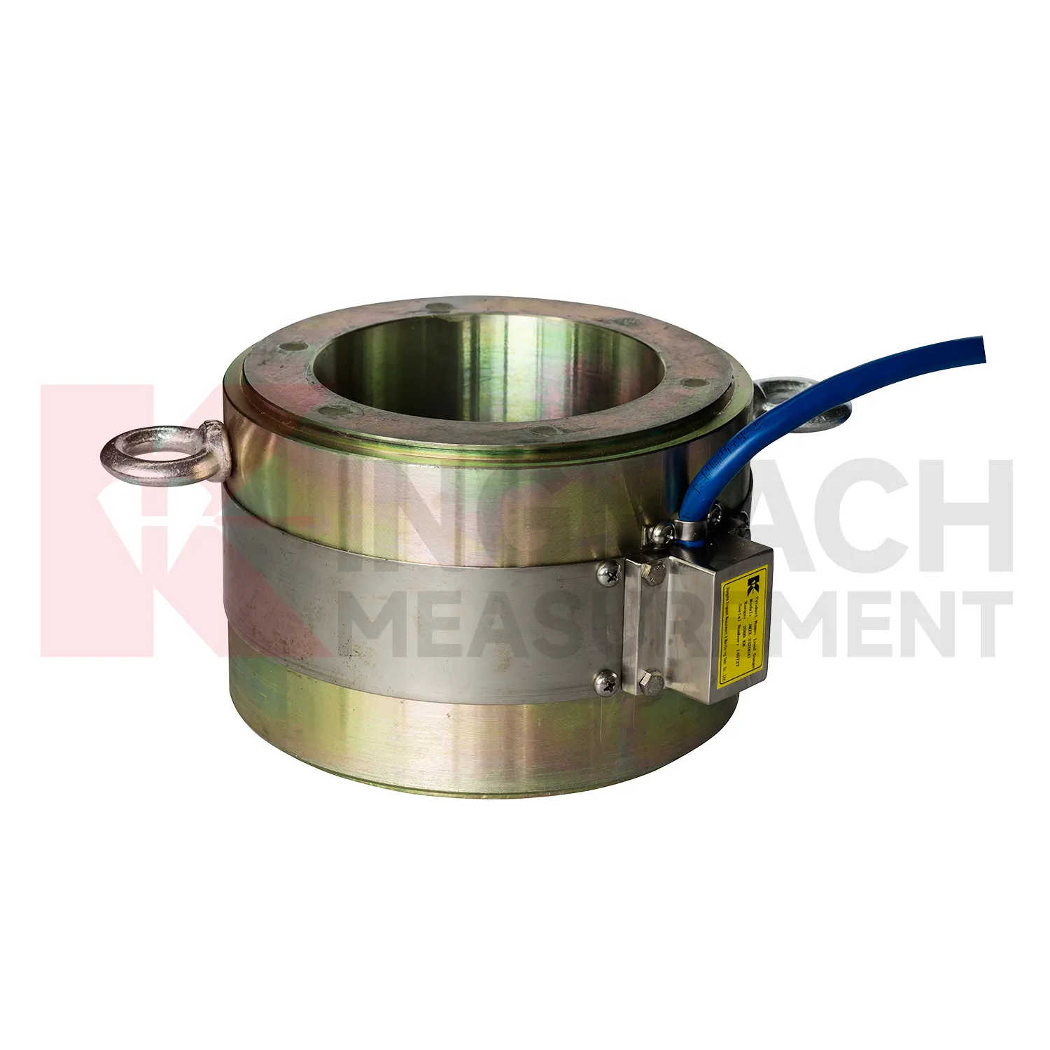
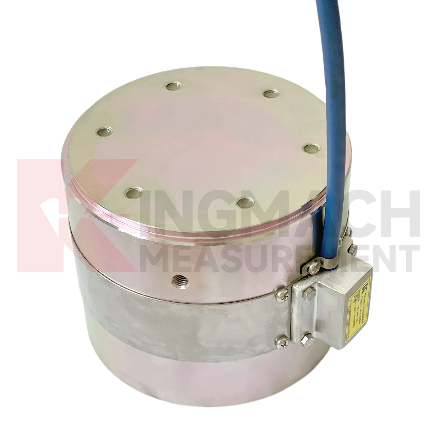
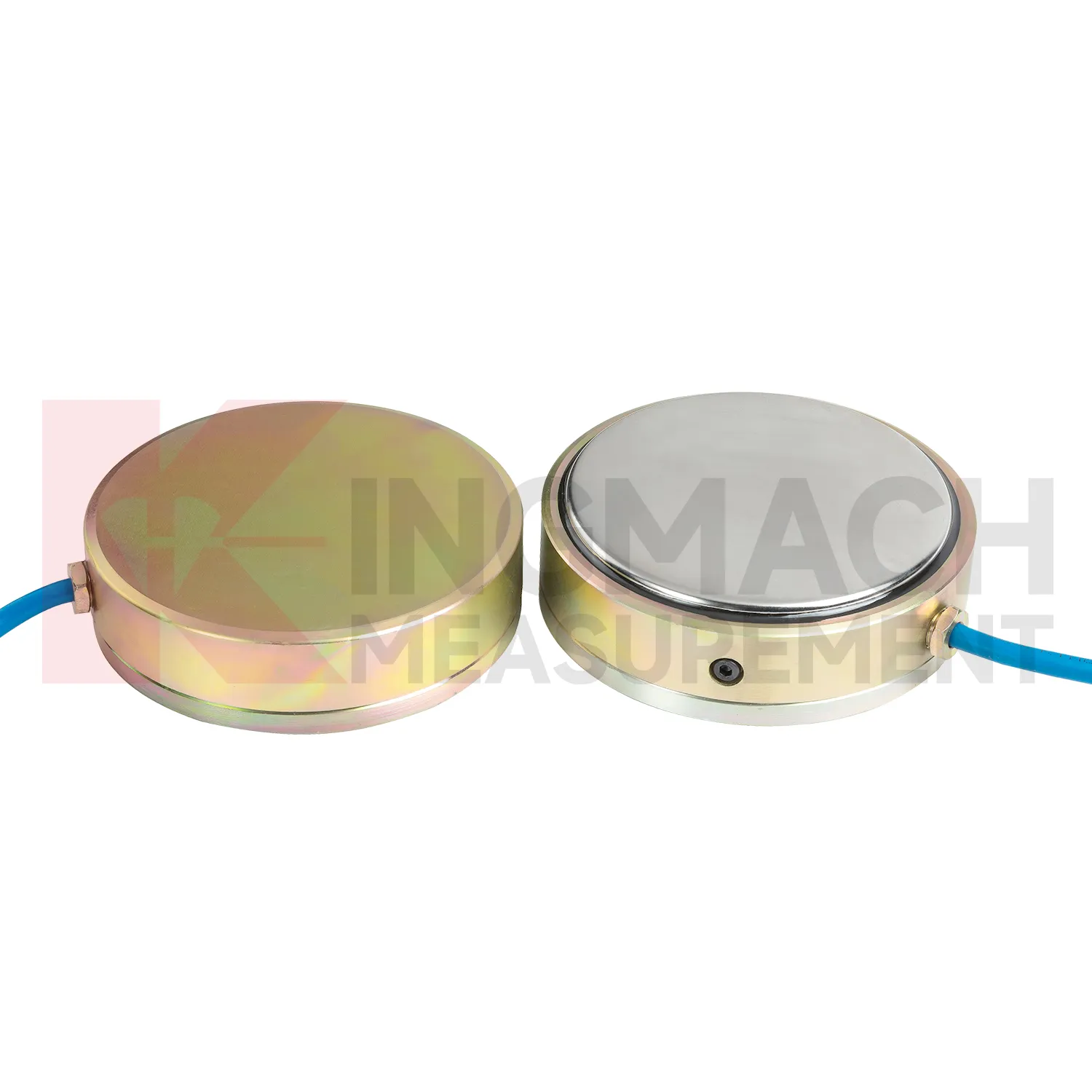
Kingmach diagram 4 wire load cell wire connection can also include pressure related sensing where soil or structural contact pressure is the main concern. The JMZX-50XXAT/ATM earth pressure cell family is listed in 0.3 MPa, 0.6 MPa, 1 MPa, 2 MPa, 4 MPa, 6 MPa, and 8 MPa ranges, with 0.001 MPa pressure resolution, 0.5%FS pressure accuracy, and ±0.5°C temperature accuracy. The product information also refers to high strength elastic steel, waterproof and durable construction, a 50 year design life, 800 stored measurement sets, and automated acquisition support. For retaining structures, embankments, dams, tunnels, and foundation pits, those pressure records help engineers understand whether earth load, water influence, compaction, or excavation stage changes are affecting the structure. Kingmach's broader monitoring catalog allows these readings to be compared with settlement, water pressure, displacement, and tilt. That connection is important because pressure change without movement may still indicate a developing load redistribution that deserves closer inspection. The same site places these instruments within a wider monitoring range, including piezometers, water level meters, displacement transducers, settlement sensors, tiltmeters, cables, data loggers, and software. That wider range helps when a project needs force data to be compared with movement, water, and temperature records.
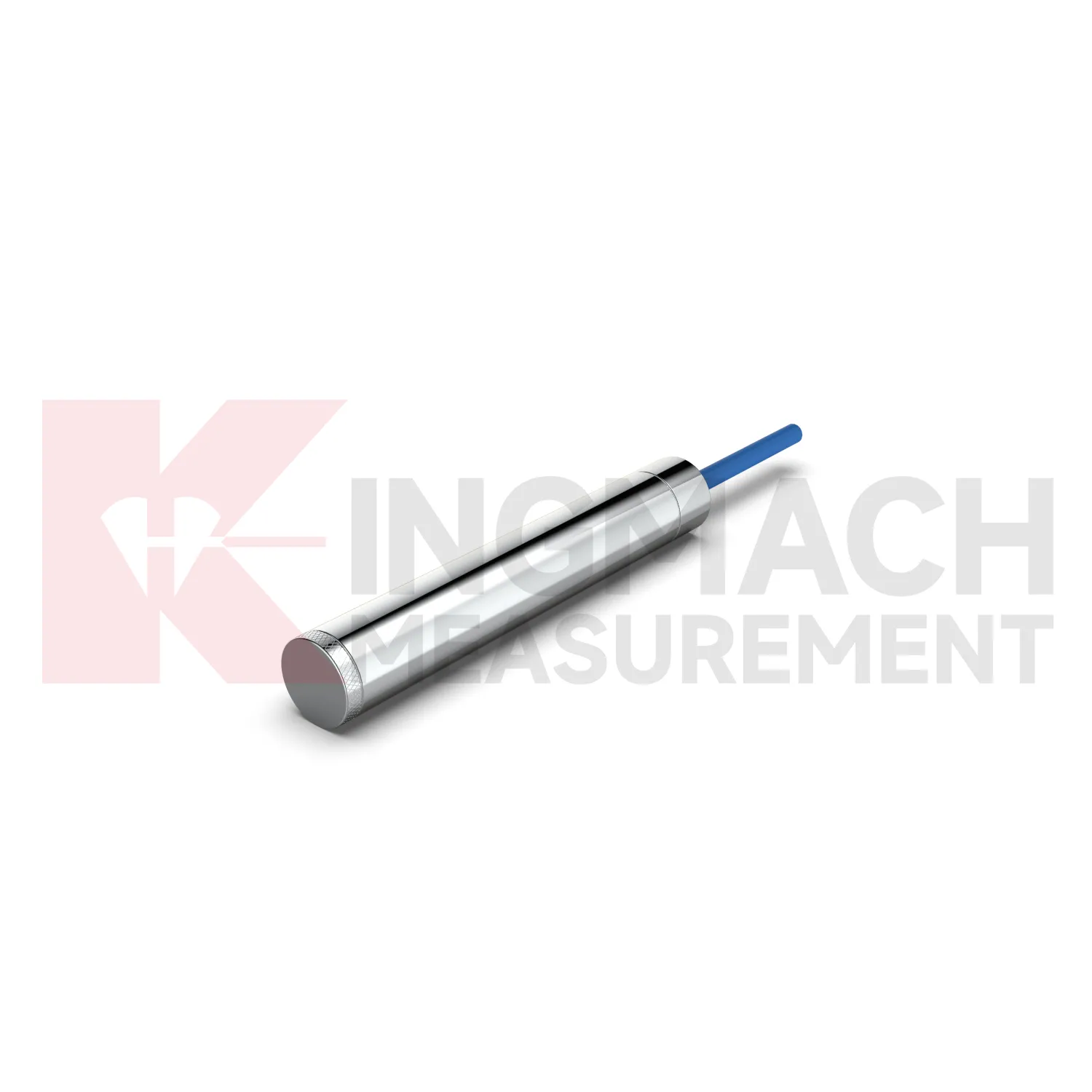
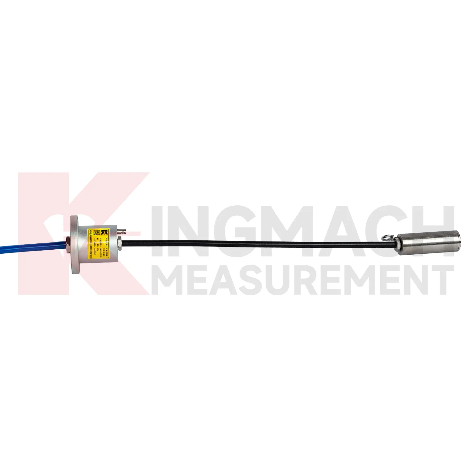
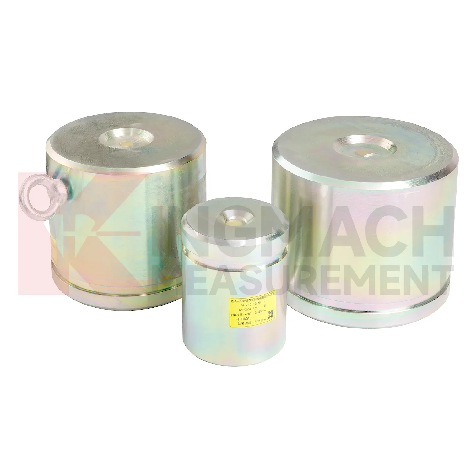
Application of diagram 4 wire load cell wire connection
In foundation pit projects, diagram 4 wire load cell wire connection supports strut force monitoring, anchor load control, retaining wall pressure checks, and load transfer review as soil is removed. The painful part of this work is timing: force can rise quickly after excavation, rainfall, dewatering, or support adjustment, while the working area is still changing every day. The axial force meter JMZX-38XXHAT covers 200 kN to 3000 kN and provides 0.5%FS accuracy with direct kN display. For soil pressure at retaining structures, the JMZX-50XXAT/ATM earth pressure cell line covers 0.3 MPa to 8 MPa with 0.001 MPa resolution and 0.5%FS pressure accuracy. These numbers give the monitoring team enough detail to track staged construction rather than only final condition. Good use also depends on bearing plates, adequate surface strength, cable protection, waterproof connectors, and a reading plan after each excavation layer. The force record should be compared with settlement, horizontal displacement, water pressure, and nearby construction notes. If automated monitoring is used, alarm thresholds should be tied to excavation stages rather than copied across all channels. A strut close to the active excavation face may behave differently from one several levels above, even when the same instrument model is used.
The future of diagram 4 wire load cell wire connection
Future diagram 4 wire load cell wire connection networks will need better alarm logic than fixed thresholds alone. A 5 percent force rise may be routine during concrete curing, serious during anchor relaxation, or irrelevant during a temperature swing. Kingmach products with temperature correction, stored records, digital output, and compatible data acquisition provide the raw structure for richer judgment. The next technical path is multi-parameter comparison: force plus displacement, pressure plus water level, support load plus excavation stage, cable force plus temperature. AI analysis can help rank unusual patterns, but the field team still needs plain evidence: which point changed, how fast, under what condition, and whether nearby sensors agree. Digital twin platforms can make that easier when sensor locations and calibration data are reliable. As monitoring specifications become more demanding, the instruments that win trust will be the ones that keep readings traceable from installation through maintenance, not just during the first acceptance test. Good metadata will matter as much as communication speed.
Care & Maintenance of diagram 4 wire load cell wire connection
For diagram 4 wire load cell wire connection, procurement and maintenance teams should agree on records before the product reaches the site. The box should not arrive as an anonymous device. The file should contain model, range, dimensions, calibration coefficient, certificate requirements, cable length, readout method, and any custom order notes. Axial force meters are often customized, with model, range, and dimension confirmed at order and lead time often planned around 20 to 30 days. During installation, check that the delivered item matches the support diameter, bearing plate layout, and data acquisition plan. During use, keep warranty, calibration, inspection, and repair notes together with the monitoring record. Protect the sensor from overload, impact, water entry, and unauthorized rewiring. If the project changes from manual reading to automated collection, verify scaling and units before comparing new data with older values. Maintenance is easier when the administrative record is as tidy as the hardware installation. Confirm changes before handover.
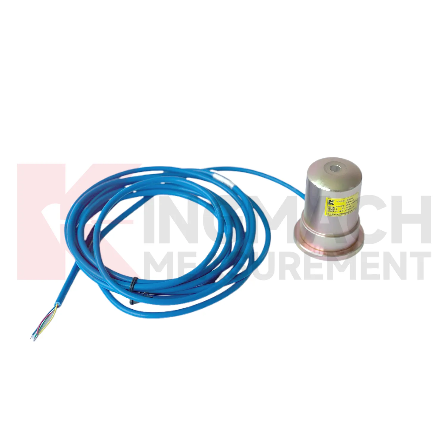
Kingmach diagram 4 wire load cell wire connection
diagram 4 wire load cell wire connection helps remove guesswork from load transfer, especially during construction stages that move quickly. Excavation, jacking, prestressing, concrete placement, reservoir impoundment, and staged traffic opening can all change force paths in hours. Kingmach smart sensor designs support digital output, long distance transmission, memory functions, and temperature correction on relevant models, which helps when manual reading windows are short. The point is not to collect more numbers for their own sake. The point is to catch a force trend early enough for the site team to check alignment, bearing plates, strut preload, grouting, drainage, or support sequence. A well installed sensor also leaves a handover trail for the owner. Later, when the structure enters service, the same point can be reviewed against seasonal effects and maintenance inspections. This keeps the force record tied to engineering behavior instead of scattered site notes. It should also record who accepted the first reading and which site event should trigger the next comparison.
FAQ
Q: When is a solid diagram 4 wire load cell wire connection more suitable than a hollow type? A: Solid models are commonly used for compression load, pile load testing, bridge pier support checks, and heavy bearing capacity measurement. Q: What specifications does the Kingmach solid load cell list? A: The JMZX-35XXHAT line lists 1000 kN to 10000 kN ranges, 0.1 kN resolution, 0.5%FS precision, and -30°C to 80°C working temperature. Q: How much overload margin is listed? A: Product information lists 20 to 50%F.S. range overload and 300 to 400%F.S. failure overload. Q: What installation errors affect accuracy? A: Eccentric loading, uneven bearing plates, side load, cable pulling, and missing zero records can all distort results. Q: What records should be kept for acceptance? A: Keep calibration coefficient, model, serial identity, load stages, temperature, zero value, and readout setting.
Reviews
Joshua Clark
We ordered a full monitoring solution including sensors and data loggers. Everything works seamlessly together. Great supplier!
Daniel Brown
Excellent environmental monitoring sensors. The data is consistent, and the system integrates smoothly with our existing setup.
Latest Inquiries
To protect the privacy of our buyers, only public service email domains like Gmail, Yahoo, and MSN will be displayed. Additionally, only a limited portion of the inquiry content will be shown.
Amelia***@gmail.comSingapore
Hello, I am looking for visualization software for monitoring system data analysis. Please let me kn...
Charlotte***@gmail.comUnited Arab Emirates
Hi, we require instrumentation cables suitable for harsh environments. Could you advise on specifica...